Remote Control Transceiver (RMT)
Introduction
The RMT (Remote Control Transceiver) peripheral was designed to act as an infrared transceiver. However, due to the flexibility of its data format, RMT can be extended to a versatile and general-purpose transceiver, transmitting or receiving many other types of signals. From the perspective of network layering, the RMT hardware contains both physical and data link layers. The physical layer defines the communication media and bit signal representation. The data link layer defines the format of an RMT frame. The minimal data unit in the frame is called the RMT symbol, which is represented by rmt_symbol_word_t in the driver.
ESP32 contains multiple channels in the RMT peripheral 1. Each channel can be independently configured as either transmitter or receiver.
Typically, the RMT peripheral can be used in the following scenarios:
Transmit or receive infrared signals, with any IR protocols, e.g., NEC
General-purpose sequence generator
Transmit signals in a hardware-controlled loop, with a finite or infinite number of times
Multi-channel simultaneous transmission
Modulate the carrier to the output signal or demodulate the carrier from the input signal
Layout of RMT Symbols
The RMT hardware defines data in its own pattern -- the RMT symbol. The diagram below illustrates the bit fields of an RMT symbol. Each symbol consists of two pairs of two values. The first value in the pair is a 15-bit value representing the signal's duration in units of RMT ticks. The second in the pair is a 1-bit value representing the signal's logic level, i.e., high or low.
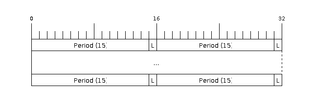
Structure of RMT symbols (L - signal level)
RMT Transmitter Overview
The data path and control path of an RMT TX channel is illustrated in the figure below:
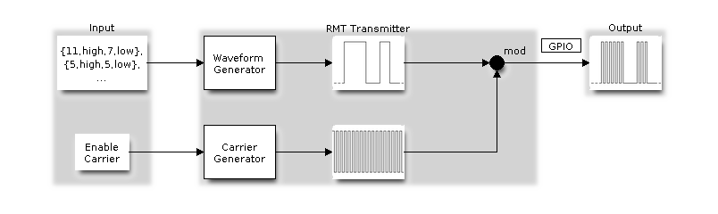
RMT Transmitter Overview
The driver encodes the user's data into RMT data format, then the RMT transmitter can generate the waveforms according to the encoding artifacts. It is also possible to modulate a high-frequency carrier signal before being routed to a GPIO pad.
RMT Receiver Overview
The data path and control path of an RMT RX channel is illustrated in the figure below:
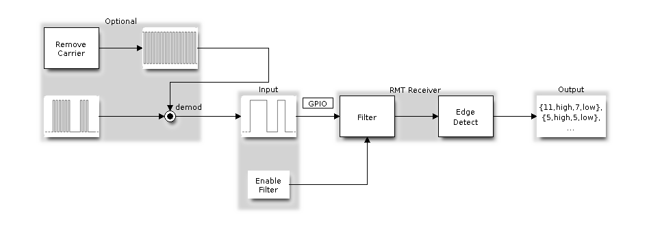
RMT Receiver Overview
The RMT receiver can sample incoming signals into RMT data format, and store the data in memory. It is also possible to tell the receiver the basic characteristics of the incoming signal, so that the signal's stop condition can be recognized, and signal glitches and noise can be filtered out. The RMT peripheral also supports demodulating the high-frequency carrier from the base signal.
Functional Overview
The description of the RMT functionality is divided into the following sections:
Resource Allocation - covers how to allocate and properly configure RMT channels. It also covers how to recycle channels and other resources when they are no longer used.
Carrier Modulation and Demodulation - describes how to modulate and demodulate the carrier signals for TX and RX channels respectively.
Register Event Callbacks - covers how to register user-provided event callbacks to receive RMT channel events.
Enable and Disable Channel - shows how to enable and disable the RMT channel.
Initiate TX Transaction - describes the steps to initiate a transaction for a TX channel.
Initiate RX Transaction - describes the steps to initiate a transaction for an RX channel.
Multiple Channels Simultaneous Transmission - describes how to collect multiple channels into a sync group so that their transmissions can be started simultaneously.
RMT Encoder - focuses on how to write a customized encoder by combining multiple primitive encoders that are provided by the driver.
Power Management - describes how different clock sources affects power consumption.
IRAM Safe - describes how disabling the cache affects the RMT driver, and tips to mitigate it.
Thread Safety - lists which APIs are guaranteed to be thread-safe by the driver.
Kconfig Options - describes the various Kconfig options supported by the RMT driver.
Resource Allocation
Both RMT TX and RX channels are represented by rmt_channel_handle_t in the driver. The driver internally manages which channels are available and hands out a free channel on request.
Install RMT TX Channel
To install an RMT TX channel, there is a configuration structure that needs to be given in advance rmt_tx_channel_config_t. The following list describes each member of the configuration structure.
rmt_tx_channel_config_t::gpio_numsets the GPIO number used by the transmitter.rmt_tx_channel_config_t::clk_srcselects the source clock for the RMT channel. The available clocks are listed inrmt_clock_source_t. Note that, the selected clock is also used by other channels, which means the user should ensure this configuration is the same when allocating other channels, regardless of TX or RX. For the effect on the power consumption of different clock sources, please refer to the Power Management section.rmt_tx_channel_config_t::resolution_hzsets the resolution of the internal tick counter. The timing parameter of the RMT signal is calculated based on this tick.rmt_tx_channel_config_t::mem_block_symbolshas a slightly different meaning based on if the DMA backend is enabled or not.If the DMA is enabled via
rmt_tx_channel_config_t::with_dma, then this field controls the size of the internal DMA buffer. To achieve a better throughput and smaller CPU overhead, you can set a larger value, e.g.,1024.If DMA is not used, this field controls the size of the dedicated memory block owned by the channel, which should be at least 64.
rmt_tx_channel_config_t::trans_queue_depthsets the depth of the internal transaction queue, the deeper the queue, the more transactions can be prepared in the backlog.rmt_tx_channel_config_t::invert_outis used to decide whether to invert the RMT signal before sending it to the GPIO pad.rmt_tx_channel_config_t::with_dmaenables the DMA backend for the channel. Using the DMA allows a significant amount of the channel's workload to be offloaded from the CPU. However, the DMA backend is not available on all ESP chips, please refer to [TRM] before you enable this option. Or you might encounter aESP_ERR_NOT_SUPPORTEDerror.rmt_tx_channel_config_t::io_loop_backenables both input and output capabilities on the channel's assigned GPIO. Thus, by binding a TX and RX channel to the same GPIO, loopback can be achieved.rmt_tx_channel_config_t::io_od_modeconfigures the channel's assigned GPIO as open-drain. When combined withrmt_tx_channel_config_t::io_loop_back, a bi-directional bus (e.g., 1-wire) can be achieved.rmt_tx_channel_config_t::intr_prioritySet the priority of the interrupt. If set to0, then the driver will use a interrupt with low or medium priority (priority level may be one of 1,2 or 3), otherwise use the priority indicated byrmt_tx_channel_config_t::intr_priority. Please use the number form (1,2,3) , not the bitmask form ((1<<1),(1<<2),(1<<3)). Please pay attention that once the interrupt priority is set, it cannot be changed untilrmt_del_channel()is called.rmt_tx_channel_config_t::backup_before_sleepenables the backup of the RMT registers before entering sleep mode. This option implies an balance between power consumption and memory usage. If the power consumption is not a concern, you can disable this option to save memory. But if you want to save power, you should enable this option to save the RMT registers before entering sleep mode, and restore them after waking up. This feature depends on specific hardware module, if you enable this flag on an unsupported chip, you will get an error message likeregister back up is not supported.
Once the rmt_tx_channel_config_t structure is populated with mandatory parameters, users can call rmt_new_tx_channel() to allocate and initialize a TX channel. This function returns an RMT channel handle if it runs correctly. Specifically, when there are no more free channels in the RMT resource pool, this function returns ESP_ERR_NOT_FOUND error. If some feature (e.g., DMA backend) is not supported by the hardware, it returns ESP_ERR_NOT_SUPPORTED error.
rmt_channel_handle_t tx_chan = NULL;
rmt_tx_channel_config_t tx_chan_config = {
    .clk_src = RMT_CLK_SRC_DEFAULT,   // select source clock
    .gpio_num = 0,                    // GPIO number
    .mem_block_symbols = 64,          // memory block size, 64 * 4 = 256 Bytes
    .resolution_hz = 1 * 1000 * 1000, // 1 MHz tick resolution, i.e., 1 tick = 1 µs
    .trans_queue_depth = 4,           // set the number of transactions that can pend in the background
    .flags.invert_out = false,        // do not invert output signal
    .flags.with_dma = false,          // do not need DMA backend
};
ESP_ERROR_CHECK(rmt_new_tx_channel(&tx_chan_config, &tx_chan));
Install RMT RX Channel
To install an RMT RX channel, there is a configuration structure that needs to be given in advance rmt_rx_channel_config_t. The following list describes each member of the configuration structure.
rmt_rx_channel_config_t::gpio_numsets the GPIO number used by the receiver.rmt_rx_channel_config_t::clk_srcselects the source clock for the RMT channel. The available clocks are listed inrmt_clock_source_t. Note that, the selected clock is also used by other channels, which means the user should ensure this configuration is the same when allocating other channels, regardless of TX or RX. For the effect on the power consumption of different clock sources, please refer to the Power Management section.rmt_rx_channel_config_t::resolution_hzsets the resolution of the internal tick counter. The timing parameter of the RMT signal is calculated based on this tick.rmt_rx_channel_config_t::mem_block_symbolshas a slightly different meaning based on whether the DMA backend is enabled.If the DMA is enabled via
rmt_rx_channel_config_t::with_dma, this field controls the maximum size of the DMA buffer.If DMA is not used, this field controls the size of the dedicated memory block owned by the channel, which should be at least 64.
rmt_rx_channel_config_t::invert_inis used to invert the input signals before it is passed to the RMT receiver. The inversion is done by the GPIO matrix instead of by the RMT peripheral.rmt_rx_channel_config_t::with_dmaenables the DMA backend for the channel. Using the DMA allows a significant amount of the channel's workload to be offloaded from the CPU. However, the DMA backend is not available on all ESP chips, please refer to [TRM] before you enable this option. Or you might encounter aESP_ERR_NOT_SUPPORTEDerror.rmt_rx_channel_config_t::io_loop_backenables both input and output capabilities on the channel's assigned GPIO. Thus, by binding a TX and RX channel to the same GPIO, loopback can be achieved.rmt_rx_channel_config_t::intr_prioritySet the priority of the interrupt. If set to0, then the driver will use a interrupt with low or medium priority (priority level may be one of 1,2 or 3), otherwise use the priority indicated byrmt_rx_channel_config_t::intr_priority. Please use the number form (1,2,3) , not the bitmask form ((1<<1),(1<<2),(1<<3)). Please pay attention that once the interrupt priority is set, it cannot be changed untilrmt_del_channel()is called.rmt_rx_channel_config_t::backup_before_sleepenables the backup of the RMT registers before entering sleep mode. This option implies an balance between power consumption and memory usage. If the power consumption is not a concern, you can disable this option to save memory. But if you want to save power, you should enable this option to save the RMT registers before entering sleep mode, and restore them after waking up. This feature depends on specific hardware module, if you enable this flag on an unsupported chip, you will get an error message likeregister back up is not supported.
Once the rmt_rx_channel_config_t structure is populated with mandatory parameters, users can call rmt_new_rx_channel() to allocate and initialize an RX channel. This function returns an RMT channel handle if it runs correctly. Specifically, when there are no more free channels in the RMT resource pool, this function returns ESP_ERR_NOT_FOUND error. If some feature (e.g., DMA backend) is not supported by the hardware, it returns ESP_ERR_NOT_SUPPORTED error.
rmt_channel_handle_t rx_chan = NULL;
rmt_rx_channel_config_t rx_chan_config = {
    .clk_src = RMT_CLK_SRC_DEFAULT,   // select source clock
    .resolution_hz = 1 * 1000 * 1000, // 1 MHz tick resolution, i.e., 1 tick = 1 µs
    .mem_block_symbols = 64,          // memory block size, 64 * 4 = 256 Bytes
    .gpio_num = 2,                    // GPIO number
    .flags.invert_in = false,         // do not invert input signal
    .flags.with_dma = false,          // do not need DMA backend
};
ESP_ERROR_CHECK(rmt_new_rx_channel(&rx_chan_config, &rx_chan));
Note
Due to a software limitation in the GPIO driver, when both TX and RX channels are bound to the same GPIO, ensure the RX Channel is initialized before the TX Channel. If the TX Channel was set up first, then during the RX Channel setup, the previous RMT TX Channel signal will be overridden by the GPIO control signal.
Uninstall RMT Channel
If a previously installed RMT channel is no longer needed, it is recommended to recycle the resources by calling rmt_del_channel(), which in return allows the underlying software and hardware resources to be reused for other purposes.
Carrier Modulation and Demodulation
The RMT transmitter can generate a carrier wave and modulate it onto the message signal. Compared to the message signal, the carrier signal's frequency is significantly higher. In addition, the user can only set the frequency and duty cycle for the carrier signal. The RMT receiver can demodulate the carrier signal from the incoming signal. Note that, carrier modulation and demodulation are not supported on all ESP chips, please refer to [TRM] before configuring the carrier, or you might encounter a ESP_ERR_NOT_SUPPORTED error.
Carrier-related configurations lie in rmt_carrier_config_t:
rmt_carrier_config_t::frequency_hzsets the carrier frequency, in Hz.rmt_carrier_config_t::duty_cyclesets the carrier duty cycle.rmt_carrier_config_t::polarity_active_lowsets the carrier polarity, i.e., on which level the carrier is applied.rmt_carrier_config_t::always_onsets whether to output the carrier even when the data transmission has finished. This configuration is only valid for the TX channel.
Note
For the RX channel, we should not set the carrier frequency exactly to the theoretical value. It is recommended to leave a tolerance for the carrier frequency. For example, in the snippet below, we set the frequency to 25 KHz, instead of the 38 KHz configured on the TX side. The reason is that reflection and refraction occur when a signal travels through the air, leading to distortion on the receiver side.
rmt_carrier_config_t tx_carrier_cfg = {
    .duty_cycle = 0.33,                 // duty cycle 33%
    .frequency_hz = 38000,              // 38 KHz
    .flags.polarity_active_low = false, // carrier should be modulated to high level
};
// modulate carrier to TX channel
ESP_ERROR_CHECK(rmt_apply_carrier(tx_chan, &tx_carrier_cfg));

rmt_carrier_config_t rx_carrier_cfg = {
    .duty_cycle = 0.33,                 // duty cycle 33%
    .frequency_hz = 25000,              // 25 KHz carrier, should be smaller than the transmitter's carrier frequency
    .flags.polarity_active_low = false, // the carrier is modulated to high level
};
// demodulate carrier from RX channel
ESP_ERROR_CHECK(rmt_apply_carrier(rx_chan, &rx_carrier_cfg));
Register Event Callbacks
When an event occurs on an RMT channel (e.g., transmission or receiving is completed), the CPU is notified of this event via an interrupt. If you have some function that needs to be called when a particular events occur, you can register a callback for that event to the RMT driver's ISR (Interrupt Service Routine) by calling rmt_tx_register_event_callbacks() and rmt_rx_register_event_callbacks() for TX and RX channel respectively. Since the registered callback functions are called in the interrupt context, the user should ensure the callback function does not block, e.g., by making sure that only FreeRTOS APIs with the FromISR suffix are called from within the function. The callback function has a boolean return value used to indicate whether a higher priority task has been unblocked by the callback.
The TX channel-supported event callbacks are listed in the rmt_tx_event_callbacks_t:
rmt_tx_event_callbacks_t::on_trans_donesets a callback function for the "trans-done" event. The function prototype is declared inrmt_tx_done_callback_t.
The RX channel-supported event callbacks are listed in the rmt_rx_event_callbacks_t:
rmt_rx_event_callbacks_t::on_recv_donesets a callback function for "receive-done" event. The function prototype is declared inrmt_rx_done_callback_t.
Note
The "receive-done" is not equivalent to "receive-finished". This callback can also be called at a "partial-receive-done" time, for many times during one receive transaction.
Users can save their own context in rmt_tx_register_event_callbacks() and rmt_rx_register_event_callbacks() as well, via the parameter user_data. The user data is directly passed to each callback function.
In the callback function, users can fetch the event-specific data that is filled by the driver in the edata. Note that the edata pointer is only valid during the callback, please do not try to save this pointer and use that outside of the callback function.
The TX-done event data is defined in rmt_tx_done_event_data_t:
rmt_tx_done_event_data_t::num_symbolsindicates the number of transmitted RMT symbols. This also reflects the size of the encoding artifacts. Please note, this value accounts for theEOFsymbol as well, which is appended by the driver to mark the end of one transaction.
The RX-complete event data is defined in rmt_rx_done_event_data_t:
rmt_rx_done_event_data_t::received_symbolspoints to the received RMT symbols. These symbols are saved in thebufferparameter of thermt_receive()function. Users should not free this receive buffer before the callback returns. If you also enabled the partial receive feature, then the user buffer will be used as a "second level buffer", where its content can be overwritten by data comes in afterwards. In this case, you should copy the received data to another place if you want to keep it or process it later.rmt_rx_done_event_data_t::num_symbolsindicates the number of received RMT symbols. This value is not larger than thebuffer_sizeparameter ofrmt_receive()function. If thebuffer_sizeis not sufficient to accommodate all the received RMT symbols, the driver only keeps the maximum number of symbols that the buffer can hold, and excess symbols are discarded or ignored.rmt_rx_done_event_data_t::is_lastindicates whether the current received buffer is the last one in the transaction. This is useful when you enable the partial reception feature byrmt_receive_config_t::extra_flags::en_partial_rx.
Enable and Disable Channel
rmt_enable() must be called in advance before transmitting or receiving RMT symbols. For TX channels, enabling a channel enables a specific interrupt and prepares the hardware to dispatch transactions. For RX channels, enabling a channel enables an interrupt, but the receiver is not started during this time, as the characteristics of the incoming signal have yet to be specified. The receiver is started in rmt_receive().
rmt_disable() does the opposite by disabling the interrupt and clearing any pending interrupts. The transmitter and receiver are disabled as well.
ESP_ERROR_CHECK(rmt_enable(tx_chan));
ESP_ERROR_CHECK(rmt_enable(rx_chan));
Initiate TX Transaction
RMT is a special communication peripheral, as it is unable to transmit raw byte streams like SPI and I2C. RMT can only send data in its own format rmt_symbol_word_t. However, the hardware does not help to convert the user data into RMT symbols, this can only be done in software by the so-called RMT Encoder. The encoder is responsible for encoding user data into RMT symbols and then writing to the RMT memory block or the DMA buffer. For how to create an RMT encoder, please refer to RMT Encoder.
Once you created an encoder, you can initiate a TX transaction by calling rmt_transmit(). This function takes several positional parameters like channel handle, encoder handle, and payload buffer. Besides, you also need to provide a transmission-specific configuration in rmt_transmit_config_t:
rmt_transmit_config_t::loop_countsets the number of transmission loops. After the transmitter has finished one round of transmission, it can restart the same transmission again if this value is not set to zero. As the loop is controlled by hardware, the RMT channel can be used to generate many periodic sequences with minimal CPU intervention.Setting
rmt_transmit_config_t::loop_countto -1 means an infinite loop transmission. In this case, the channel does not stop untilrmt_disable()is called. The "trans-done" event is not generated as well.Setting
rmt_transmit_config_t::loop_countto a positive number means finite number of iterations. In this case, the "trans-done" event is when the specified number of iterations have completed.
Note
The loop transmit feature is not supported on all ESP chips, please refer to [TRM] before you configure this option, or you might encounter
ESP_ERR_NOT_SUPPORTEDerror.rmt_transmit_config_t::eot_levelsets the output level when the transmitter finishes working or stops working by callingrmt_disable().rmt_transmit_config_t::queue_nonblockingsets whether to wait for a free slot in the transaction queue when it is full. If this value is set totrue, then the function will return with an error codeESP_ERR_INVALID_STATEwhen the queue is full. Otherwise, the function will block until a free slot is available in the queue.
Note
There is a limitation in the transmission size if the rmt_transmit_config_t::loop_count is set to non-zero, i.e., to enable the loop feature. The encoded RMT symbols should not exceed the capacity of the RMT hardware memory block size, or you might see an error message like encoding artifacts can't exceed hw memory block for loop transmission. If you have to start a large transaction by loop, you can try either of the following methods.
Increase the
rmt_tx_channel_config_t::mem_block_symbols. This approach does not work if the DMA backend is also enabled.Customize an encoder and construct an infinite loop in the encoding function. See also RMT Encoder.
Internally, rmt_transmit() constructs a transaction descriptor and sends it to a job queue, which is dispatched in the ISR. So it is possible that the transaction is not started yet when rmt_transmit() returns. You cannot recycle or modify the payload buffer until the transaction is finished. You can get the transaction completion event by registering a callback function via rmt_tx_register_event_callbacks(). To ensure all pending transactions to complete, you can also use rmt_tx_wait_all_done().
Multiple Channels Simultaneous Transmission
In some real-time control applications (e.g., to make two robotic arms move simultaneously), you do not want any time drift between different channels. The RMT driver can help to manage this by creating a so-called Sync Manager. The sync manager is represented by rmt_sync_manager_handle_t in the driver. The procedure of RMT sync transmission is shown as follows:
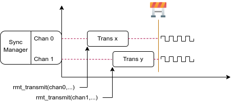
RMT TX Sync
Install RMT Sync Manager
To create a sync manager, the user needs to tell which channels are going to be managed in the rmt_sync_manager_config_t:
rmt_sync_manager_config_t::tx_channel_arraypoints to the array of TX channels to be managed.rmt_sync_manager_config_t::array_sizesets the number of channels to be managed.
rmt_new_sync_manager() can return a manager handle on success. This function could also fail due to various errors such as invalid arguments, etc. Especially, when the sync manager has been installed before, and there are no hardware resources to create another manager, this function reports ESP_ERR_NOT_FOUND error. In addition, if the sync manager is not supported by the hardware, it reports a ESP_ERR_NOT_SUPPORTED error. Please refer to [TRM] before using the sync manager feature.
Start Transmission Simultaneously
For any managed TX channel, it does not start the machine until rmt_transmit() has been called on all channels in rmt_sync_manager_config_t::tx_channel_array. Before that, the channel is just put in a waiting state. TX channels will usually complete their transactions at different times due to differing transactions, thus resulting in a loss of sync. So before restarting a simultaneous transmission, the user needs to call rmt_sync_reset() to synchronize all channels again.
Calling rmt_del_sync_manager() can recycle the sync manager and enable the channels to initiate transactions independently afterward.
rmt_channel_handle_t tx_channels[2] = {NULL}; // declare two channels
int tx_gpio_number[2] = {0, 2};
// install channels one by one
for (int i = 0; i < 2; i++) {
    rmt_tx_channel_config_t tx_chan_config = {
        .clk_src = RMT_CLK_SRC_DEFAULT,       // select source clock
        .gpio_num = tx_gpio_number[i],    // GPIO number
        .mem_block_symbols = 64,          // memory block size, 64 * 4 = 256 Bytes
        .resolution_hz = 1 * 1000 * 1000, // 1 MHz resolution
        .trans_queue_depth = 1,           // set the number of transactions that can pend in the background
    };
    ESP_ERROR_CHECK(rmt_new_tx_channel(&tx_chan_config, &tx_channels[i]));
}
// install sync manager
rmt_sync_manager_handle_t synchro = NULL;
rmt_sync_manager_config_t synchro_config = {
    .tx_channel_array = tx_channels,
    .array_size = sizeof(tx_channels) / sizeof(tx_channels[0]),
};
ESP_ERROR_CHECK(rmt_new_sync_manager(&synchro_config, &synchro));

ESP_ERROR_CHECK(rmt_transmit(tx_channels[0], led_strip_encoders[0], led_data, led_num * 3, &transmit_config));
// tx_channels[0] does not start transmission until call of `rmt_transmit()` for tx_channels[1] returns
ESP_ERROR_CHECK(rmt_transmit(tx_channels[1], led_strip_encoders[1], led_data, led_num * 3, &transmit_config));
Initiate RX Transaction
As also discussed in the Enable and Disable Channel, calling rmt_enable() does not prepare an RX to receive RMT symbols. The user needs to specify the basic characteristics of the incoming signals in rmt_receive_config_t:
rmt_receive_config_t::signal_range_min_nsspecifies the minimal valid pulse duration in either high or low logic levels. A pulse width that is smaller than this value is treated as a glitch, and ignored by the hardware.rmt_receive_config_t::signal_range_max_nsspecifies the maximum valid pulse duration in either high or low logic levels. A pulse width that is bigger than this value is treated as Stop Signal, and the receiver generates receive-complete event immediately.If the incoming packet is long, that they cannot be stored in the user buffer at once, you can enable the partial reception feature by setting
rmt_receive_config_t::extra_flags::en_partial_rxtotrue. In this case, the driver invokesrmt_rx_event_callbacks_t::on_recv_donecallback multiple times during one transaction, when the user buffer is almost full. You can check the value of :cpp:member::rmt_rx_done_event_data_t::is_last to know if the transaction is about to finish. Please note this features is not supported on all ESP series chips because it relies on hardware abilities like "ping-pong receive" or "DMA receive".
The RMT receiver starts the RX machine after the user calls rmt_receive() with the provided configuration above. Note that, this configuration is transaction specific, which means, to start a new round of reception, the user needs to set the rmt_receive_config_t again. The receiver saves the incoming signals into its internal memory block or DMA buffer, in the format of rmt_symbol_word_t.
Due to the limited size of the memory block, the RMT receiver can only save short frames whose length is not longer than the memory block capacity. Long frames are truncated by the hardware, and the driver reports an error message: hw buffer too small, received symbols truncated.
The copy destination should be provided in the buffer parameter of rmt_receive() function. If this buffer overflows due to an insufficient buffer size, the receiver can continue to work, but overflowed symbols are dropped and the following error message is reported: user buffer too small, received symbols truncated. Please take care of the lifecycle of the buffer parameter, ensuring that the buffer is not recycled before the receiver is finished or stopped.
The receiver is stopped by the driver when it finishes working, i.e., receive a signal whose duration is bigger than rmt_receive_config_t::signal_range_max_ns. The user needs to call rmt_receive() again to restart the receiver, if necessary. The user can get the received data in the rmt_rx_event_callbacks_t::on_recv_done callback. See also Register Event Callbacks for more information.
static bool example_rmt_rx_done_callback(rmt_channel_handle_t channel, const rmt_rx_done_event_data_t *edata, void *user_data)
{
    BaseType_t high_task_wakeup = pdFALSE;
    QueueHandle_t receive_queue = (QueueHandle_t)user_data;
    // send the received RMT symbols to the parser task
    xQueueSendFromISR(receive_queue, edata, &high_task_wakeup);
    // return whether any task is woken up
    return high_task_wakeup == pdTRUE;
}

QueueHandle_t receive_queue = xQueueCreate(1, sizeof(rmt_rx_done_event_data_t));
rmt_rx_event_callbacks_t cbs = {
    .on_recv_done = example_rmt_rx_done_callback,
};
ESP_ERROR_CHECK(rmt_rx_register_event_callbacks(rx_channel, &cbs, receive_queue));

// the following timing requirement is based on NEC protocol
rmt_receive_config_t receive_config = {
    .signal_range_min_ns = 1250,     // the shortest duration for NEC signal is 560 µs, 1250 ns < 560 µs, valid signal is not treated as noise
    .signal_range_max_ns = 12000000, // the longest duration for NEC signal is 9000 µs, 12000000 ns > 9000 µs, the receive does not stop early
};

rmt_symbol_word_t raw_symbols[64]; // 64 symbols should be sufficient for a standard NEC frame
// ready to receive
ESP_ERROR_CHECK(rmt_receive(rx_channel, raw_symbols, sizeof(raw_symbols), &receive_config));
// wait for the RX-done signal
rmt_rx_done_event_data_t rx_data;
xQueueReceive(receive_queue, &rx_data, portMAX_DELAY);
// parse the received symbols
example_parse_nec_frame(rx_data.received_symbols, rx_data.num_symbols);
RMT Encoder
An RMT encoder is part of the RMT TX transaction, whose responsibility is to generate and write the correct RMT symbols into hardware memory or DMA buffer at a specific time. There are some special restrictions for an encoding function:
During a single transaction, the encoding function may be called multiple times. This is necessary because the target RMT memory block cannot hold all the artifacts at once. To overcome this limitation, the driver utilizes a ping-pong approach, where the encoding session is divided into multiple parts. This means that the encoder needs to keep track of its state to continue encoding from where it left off in the previous part.
The encoding function is running in the ISR context. To speed up the encoding session, it is highly recommended to put the encoding function into IRAM. This can also avoid the cache miss during encoding.
To help get started with the RMT driver faster, some commonly used encoders are provided out-of-the-box. They can either work alone or be chained together into a new encoder. See also Composite Pattern for the principle behind it. The driver has defined the encoder interface in rmt_encoder_t, it contains the following functions:
rmt_encoder_t::encodeis the fundamental function of an encoder. This is where the encoding session happens.The function might be called multiple times within a single transaction. The encode function should return the state of the current encoding session.
The supported states are listed in the
rmt_encode_state_t. If the result containsRMT_ENCODING_COMPLETE, it means the current encoder has finished work.If the result contains
RMT_ENCODING_MEM_FULL, the program needs to yield from the current session, as there is no space to save more encoding artifacts.
rmt_encoder_t::resetshould reset the encoder state back to the initial state (the RMT encoder is stateful).If the RMT transmitter is manually stopped without resetting its corresponding encoder, subsequent encoding session can be erroneous.
This function is also called implicitly in
rmt_disable().
rmt_encoder_t::delshould free the resources allocated by the encoder.
Copy Encoder
A copy encoder is created by calling rmt_new_copy_encoder(). A copy encoder's main functionality is to copy the RMT symbols from user space into the driver layer. It is usually used to encode const data, i.e., data does not change at runtime after initialization such as the leading code in the IR protocol.
A configuration structure rmt_copy_encoder_config_t should be provided in advance before calling rmt_new_copy_encoder(). Currently, this configuration is reserved for future expansion, and has no specific use or setting items for now.
Bytes Encoder
A bytes encoder is created by calling rmt_new_bytes_encoder(). The bytes encoder's main functionality is to convert the user space byte stream into RMT symbols dynamically. It is usually used to encode dynamic data, e.g., the address and command fields in the IR protocol.
A configuration structure rmt_bytes_encoder_config_t should be provided in advance before calling rmt_new_bytes_encoder():
rmt_bytes_encoder_config_t::bit0andrmt_bytes_encoder_config_t::bit1are necessary to specify the encoder how to represent bit zero and bit one in the format ofrmt_symbol_word_t.rmt_bytes_encoder_config_t::msb_firstsets the bit endianness of each byte. If it is set to true, the encoder encodes the Most Significant Bit first. Otherwise, it encodes the Least Significant Bit first.
Besides the primitive encoders provided by the driver, the user can implement his own encoder by chaining the existing encoders together. A common encoder chain is shown as follows:
RMT Encoder Chain
Simple Callback Encoder
A simple callback encoder is created by calling rmt_new_simple_encoder(). The simple callback encoder allows you to provide a callback that reads data from userspace and writes symbols to the output stream without having to chain other encoders. The callback itself gets a pointer to the data passed to rmt_transmit(), a counter indicating the amount of symbols already written by the callback in this transmission, and a pointer where to write the encoded RMT symbols as well as the free space there. If the space is not enough for the callback to encode something, it can return 0 and the RMT will wait for previous symbols to be transmitted and call the callback again, now with more space available. If the callback successfully writes RMT symbols, it should return the number of symbols written.
A configuration structure rmt_simple_encoder_config_t should be provided in advance before calling rmt_new_simple_encoder():
rmt_simple_encoder_config_t::callbackandrmt_simple_encoder_config_t::argprovide the callback function and an opaque argument that will be passed to that function.rmt_simple_encoder_config_t::min_chunk_sizespecifies the minimum amount of free space, in symbols, the encoder will be always be able to write some data to. In other words, when this amount of free space is passed to the encoder, it should never return 0 (except when the encoder is done encoding symbols).
While the functionality of an encoding process using the simple callback encoder can usually also realized by chaining other encoders, the simple callback can be more easy to understand and maintain than an encoder chain.
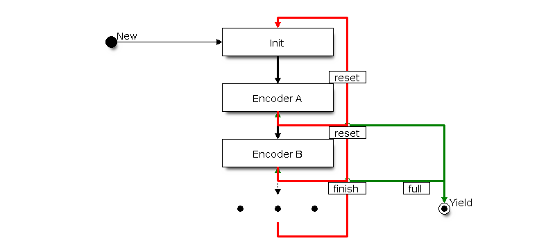
Customize RMT Encoder for NEC Protocol
This section demonstrates how to write an NEC encoder. The NEC IR protocol uses pulse distance encoding of the message bits. Each pulse burst is 562.5 µs in length, logical bits are transmitted as follows. It is worth mentioning that the least significant bit of each byte is sent first.
Logical
0: a562.5 µspulse burst followed by a562.5 µsspace, with a total transmit time of1.125 msLogical
1: a562.5 µspulse burst followed by a1.6875 msspace, with a total transmit time of2.25 ms
When a key is pressed on the remote controller, the transmitted message includes the following elements in the specified order:
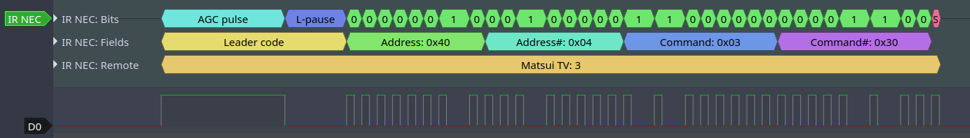
IR NEC Frame
9 msleading pulse burst, also called the "AGC pulse"4.5 msspace8-bit address for the receiving device
8-bit logical inverse of the address
8-bit command
8-bit logical inverse of the command
a final
562.5 µspulse burst to signify the end of message transmission
Then you can construct the NEC rmt_encoder_t::encode function in the same order, for example:
// IR NEC scan code representation
typedef struct {
    uint16_t address;
    uint16_t command;
} ir_nec_scan_code_t;

// construct an encoder by combining primitive encoders
typedef struct {
    rmt_encoder_t base;           // the base "class" declares the standard encoder interface
    rmt_encoder_t *copy_encoder;  // use the copy_encoder to encode the leading and ending pulse
    rmt_encoder_t *bytes_encoder; // use the bytes_encoder to encode the address and command data
    rmt_symbol_word_t nec_leading_symbol; // NEC leading code with RMT representation
    rmt_symbol_word_t nec_ending_symbol;  // NEC ending code with RMT representation
    int state; // record the current encoding state, i.e., we are in which encoding phase
} rmt_ir_nec_encoder_t;

static size_t rmt_encode_ir_nec(rmt_encoder_t *encoder, rmt_channel_handle_t channel, const void *primary_data, size_t data_size, rmt_encode_state_t *ret_state)
{
    rmt_ir_nec_encoder_t *nec_encoder = __containerof(encoder, rmt_ir_nec_encoder_t, base);
    rmt_encode_state_t session_state = RMT_ENCODING_RESET;
    rmt_encode_state_t state = RMT_ENCODING_RESET;
    size_t encoded_symbols = 0;
    ir_nec_scan_code_t *scan_code = (ir_nec_scan_code_t *)primary_data;
    rmt_encoder_handle_t copy_encoder = nec_encoder->copy_encoder;
    rmt_encoder_handle_t bytes_encoder = nec_encoder->bytes_encoder;
    switch (nec_encoder->state) {
    case 0: // send leading code
        encoded_symbols += copy_encoder->encode(copy_encoder, channel, &nec_encoder->nec_leading_symbol,
                                                sizeof(rmt_symbol_word_t), &session_state);
        if (session_state & RMT_ENCODING_COMPLETE) {
            nec_encoder->state = 1; // we can only switch to the next state when the current encoder finished
        }
        if (session_state & RMT_ENCODING_MEM_FULL) {
            state |= RMT_ENCODING_MEM_FULL;
            goto out; // yield if there is no free space to put other encoding artifacts
        }
    // fall-through
    case 1: // send address
        encoded_symbols += bytes_encoder->encode(bytes_encoder, channel, &scan_code->address, sizeof(uint16_t), &session_state);
        if (session_state & RMT_ENCODING_COMPLETE) {
            nec_encoder->state = 2; // we can only switch to the next state when the current encoder finished
        }
        if (session_state & RMT_ENCODING_MEM_FULL) {
            state |= RMT_ENCODING_MEM_FULL;
            goto out; // yield if there is no free space to put other encoding artifacts
        }
    // fall-through
    case 2: // send command
        encoded_symbols += bytes_encoder->encode(bytes_encoder, channel, &scan_code->command, sizeof(uint16_t), &session_state);
        if (session_state & RMT_ENCODING_COMPLETE) {
            nec_encoder->state = 3; // we can only switch to the next state when the current encoder finished
        }
        if (session_state & RMT_ENCODING_MEM_FULL) {
            state |= RMT_ENCODING_MEM_FULL;
            goto out; // yield if there is no free space to put other encoding artifacts
        }
    // fall-through
    case 3: // send ending code
        encoded_symbols += copy_encoder->encode(copy_encoder, channel, &nec_encoder->nec_ending_symbol,
                                                sizeof(rmt_symbol_word_t), &session_state);
        if (session_state & RMT_ENCODING_COMPLETE) {
            nec_encoder->state = RMT_ENCODING_RESET; // back to the initial encoding session
            state |= RMT_ENCODING_COMPLETE; // telling the caller the NEC encoding has finished
        }
        if (session_state & RMT_ENCODING_MEM_FULL) {
            state |= RMT_ENCODING_MEM_FULL;
            goto out; // yield if there is no free space to put other encoding artifacts
        }
    }
out:
    *ret_state = state;
    return encoded_symbols;
}
A full sample code can be found in peripherals/rmt/ir_nec_transceiver. In the above snippet, we use a switch-case and several goto statements to implement a Finite-state machine . With this pattern, users can construct much more complex IR protocols.
Power Management
When power management is enabled, i.e., CONFIG_PM_ENABLE is on, the system may adjust or disable the clock source before going to sleep. As a result, the time base inside the RMT can't work as expected.
The driver can prevent the above issue by creating a power management lock. The lock type is set based on different clock sources. The driver will acquire the lock in rmt_enable(), and release it in rmt_disable(). That means, any RMT transactions in between these two functions are guaranteed to work correctly, regardless of the power management strategy. The clock source won't be disabled or adjusted its frequency during this time.
IRAM Safe
By default, the RMT interrupt is deferred when the Cache is disabled for reasons like writing or erasing the main Flash. Thus the transaction-done interrupt does not get handled in time, which is not acceptable in a real-time application. What is worse, when the RMT transaction relies on ping-pong interrupt to successively encode or copy RMT symbols, a delayed interrupt can lead to an unpredictable result.
There is a Kconfig option CONFIG_RMT_ISR_IRAM_SAFE that has the following features:
Enable the interrupt being serviced even when the cache is disabled
Place all functions used by the ISR into IRAM 2
Place the driver object into DRAM in case it is mapped to PSRAM by accident
This Kconfig option allows the interrupt handler to run while the cache is disabled but comes at the cost of increased IRAM consumption.
Another Kconfig option CONFIG_RMT_RECV_FUNC_IN_IRAM can place rmt_receive() into the IRAM as well. So that the receive function can be used even when the flash cache is disabled.
Thread Safety
The factory function rmt_new_tx_channel(), rmt_new_rx_channel() and rmt_new_sync_manager() are guaranteed to be thread-safe by the driver, which means, user can call them from different RTOS tasks without protection by extra locks.
Other functions that take the rmt_channel_handle_t and rmt_sync_manager_handle_t as the first positional parameter, are not thread-safe. which means the user should avoid calling them from multiple tasks.
The following functions are allowed to use under ISR context as well.
Kconfig Options
CONFIG_RMT_ISR_IRAM_SAFE controls whether the default ISR handler can work when cache is disabled, see also IRAM Safe for more information.
CONFIG_RMT_ENABLE_DEBUG_LOG is used to enable the debug log at the cost of increased firmware binary size.
CONFIG_RMT_RECV_FUNC_IN_IRAM controls where to place the RMT receive function (IRAM or Flash), see IRAM Safe for more information.
Application Examples
RMT-based RGB LED strip customized encoder: peripherals/rmt/led_strip
RMT IR NEC protocol encoding and decoding: peripherals/rmt/ir_nec_transceiver
RMT transactions in queue: peripherals/rmt/musical_buzzer
RMT-based stepper motor with S-curve algorithm: : peripherals/rmt/stepper_motor
RMT infinite loop for driving DShot ESC: peripherals/rmt/dshot_esc
RMT simulate 1-wire protocol (take DS18B20 as example): peripherals/rmt/onewire
FAQ
Why the RMT transmits more data than expected?
The encoding for the RMT transmission is carried out within the ISR context. Should the RMT encoding process be prolonged (for example, through logging or tracing the procedure) or if it is delayed due to interrupt latency and preemptive interrupts, the hardware transmitter might read from the memory before the encoder has written to it. Consequently, the transmitter would end up sending outdated data. Although it's not possible to instruct the transmitter to pause and wait, this issue can be mitigated by employing a combination of the following strategies:
Increase the
rmt_tx_channel_config_t::mem_block_symbols, in steps of 64.Place the encoding function in the IRAM with
IRAM_ATTRattribute.Enable the
rmt_tx_channel_config_t::with_dmaif DMA is available.Install the RMT driver on a separate CPU core to avoid competing for the same CPU resources with other interrupt heavy peripherals (e.g. WiFi, Bluetooth).
API Reference
Header File
This header file can be included with:
#include "driver/rmt_tx.h"
This header file is a part of the API provided by the
esp_driver_rmtcomponent. To declare that your component depends onesp_driver_rmt, add the following to your CMakeLists.txt:REQUIRES esp_driver_rmt
or
PRIV_REQUIRES esp_driver_rmt
Functions
-
esp_err_t rmt_new_tx_channel(const rmt_tx_channel_config_t *config, rmt_channel_handle_t *ret_chan)
Create a RMT TX channel.
- Parameters
config -- [in] TX channel configurations
ret_chan -- [out] Returned generic RMT channel handle
- Returns
ESP_OK: Create RMT TX channel successfully
ESP_ERR_INVALID_ARG: Create RMT TX channel failed because of invalid argument
ESP_ERR_NO_MEM: Create RMT TX channel failed because out of memory
ESP_ERR_NOT_FOUND: Create RMT TX channel failed because all RMT channels are used up and no more free one
ESP_ERR_NOT_SUPPORTED: Create RMT TX channel failed because some feature is not supported by hardware, e.g. DMA feature is not supported by hardware
ESP_FAIL: Create RMT TX channel failed because of other error
-
esp_err_t rmt_transmit(rmt_channel_handle_t tx_channel, rmt_encoder_handle_t encoder, const void *payload, size_t payload_bytes, const rmt_transmit_config_t *config)
Transmit data by RMT TX channel.
Note
This function constructs a transaction descriptor then pushes to a queue. The transaction will not start immediately if there's another one under processing. Based on the setting of
rmt_transmit_config_t::queue_nonblocking, if there're too many transactions pending in the queue, this function can block until it has free slot, otherwise just return quickly.Note
The payload data to be transmitted will be encoded into RMT symbols by the specific
encoder.Note
You CAN'T modify the
payloadduring the transmission, it should be kept valid until the transmission is finished.- Parameters
tx_channel -- [in] RMT TX channel that created by
rmt_new_tx_channel()encoder -- [in] RMT encoder that created by various factory APIs like
rmt_new_bytes_encoder()payload -- [in] The raw data to be encoded into RMT symbols
payload_bytes -- [in] Size of the
payloadin bytesconfig -- [in] Transmission specific configuration
- Returns
ESP_OK: Transmit data successfully
ESP_ERR_INVALID_ARG: Transmit data failed because of invalid argument
ESP_ERR_INVALID_STATE: Transmit data failed because channel is not enabled
ESP_ERR_NOT_SUPPORTED: Transmit data failed because some feature is not supported by hardware, e.g. unsupported loop count
ESP_FAIL: Transmit data failed because of other error
-
esp_err_t rmt_tx_wait_all_done(rmt_channel_handle_t tx_channel, int timeout_ms)
Wait for all pending TX transactions done.
Note
This function will block forever if the pending transaction can't be finished within a limited time (e.g. an infinite loop transaction). See also
rmt_disable()for how to terminate a working channel.- Parameters
tx_channel -- [in] RMT TX channel that created by
rmt_new_tx_channel()timeout_ms -- [in] Wait timeout, in ms. Specially, -1 means to wait forever.
- Returns
ESP_OK: Flush transactions successfully
ESP_ERR_INVALID_ARG: Flush transactions failed because of invalid argument
ESP_ERR_TIMEOUT: Flush transactions failed because of timeout
ESP_FAIL: Flush transactions failed because of other error
-
esp_err_t rmt_tx_register_event_callbacks(rmt_channel_handle_t tx_channel, const rmt_tx_event_callbacks_t *cbs, void *user_data)
Set event callbacks for RMT TX channel.
Note
User can deregister a previously registered callback by calling this function and setting the callback member in the
cbsstructure to NULL.Note
When CONFIG_RMT_ISR_IRAM_SAFE is enabled, the callback itself and functions called by it should be placed in IRAM. The variables used in the function should be in the SRAM as well. The
user_datashould also reside in SRAM.- Parameters
tx_channel -- [in] RMT generic channel that created by
rmt_new_tx_channel()cbs -- [in] Group of callback functions
user_data -- [in] User data, which will be passed to callback functions directly
- Returns
ESP_OK: Set event callbacks successfully
ESP_ERR_INVALID_ARG: Set event callbacks failed because of invalid argument
ESP_FAIL: Set event callbacks failed because of other error
-
esp_err_t rmt_new_sync_manager(const rmt_sync_manager_config_t *config, rmt_sync_manager_handle_t *ret_synchro)
Create a synchronization manager for multiple TX channels, so that the managed channel can start transmitting at the same time.
Note
All the channels to be managed should be enabled by
rmt_enable()before put them into sync manager.- Parameters
config -- [in] Synchronization manager configuration
ret_synchro -- [out] Returned synchronization manager handle
- Returns
ESP_OK: Create sync manager successfully
ESP_ERR_INVALID_ARG: Create sync manager failed because of invalid argument
ESP_ERR_NOT_SUPPORTED: Create sync manager failed because it is not supported by hardware
ESP_ERR_INVALID_STATE: Create sync manager failed because not all channels are enabled
ESP_ERR_NO_MEM: Create sync manager failed because out of memory
ESP_ERR_NOT_FOUND: Create sync manager failed because all sync controllers are used up and no more free one
ESP_FAIL: Create sync manager failed because of other error
-
esp_err_t rmt_del_sync_manager(rmt_sync_manager_handle_t synchro)
Delete synchronization manager.
- Parameters
synchro -- [in] Synchronization manager handle returned from
rmt_new_sync_manager()- Returns
ESP_OK: Delete the synchronization manager successfully
ESP_ERR_INVALID_ARG: Delete the synchronization manager failed because of invalid argument
ESP_FAIL: Delete the synchronization manager failed because of other error
-
esp_err_t rmt_sync_reset(rmt_sync_manager_handle_t synchro)
Reset synchronization manager.
- Parameters
synchro -- [in] Synchronization manager handle returned from
rmt_new_sync_manager()- Returns
ESP_OK: Reset the synchronization manager successfully
ESP_ERR_INVALID_ARG: Reset the synchronization manager failed because of invalid argument
ESP_FAIL: Reset the synchronization manager failed because of other error
Structures
-
struct rmt_tx_event_callbacks_t
Group of RMT TX callbacks.
Note
The callbacks are all running under ISR environment
Note
When CONFIG_RMT_ISR_IRAM_SAFE is enabled, the callback itself and functions called by it should be placed in IRAM. The variables used in the function should be in the SRAM as well.
Public Members
-
rmt_tx_done_callback_t on_trans_done
Event callback, invoked when transmission is finished
-
rmt_tx_done_callback_t on_trans_done
-
struct rmt_tx_channel_config_t
RMT TX channel specific configuration.
Public Members
-
gpio_num_t gpio_num
GPIO number used by RMT TX channel. Set to -1 if unused
-
rmt_clock_source_t clk_src
Clock source of RMT TX channel, channels in the same group must use the same clock source
-
uint32_t resolution_hz
Channel clock resolution, in Hz
-
size_t mem_block_symbols
Size of memory block, in number of
rmt_symbol_word_t, must be an even. In the DMA mode, this field controls the DMA buffer size, it can be set to a large value; In the normal mode, this field controls the number of RMT memory block that will be used by the channel.
-
size_t trans_queue_depth
Depth of internal transfer queue, increase this value can support more transfers pending in the background
-
int intr_priority
RMT interrupt priority, if set to 0, the driver will try to allocate an interrupt with a relative low priority (1,2,3)
-
uint32_t invert_out
Whether to invert the RMT channel signal before output to GPIO pad
-
uint32_t with_dma
If set, the driver will allocate an RMT channel with DMA capability
-
uint32_t io_loop_back
The signal output from the GPIO will be fed to the input path as well
-
uint32_t io_od_mode
Configure the GPIO as open-drain mode
-
uint32_t backup_before_sleep
If set, the driver will backup/restore the RMT registers before/after entering/exist sleep mode. By this approach, the system can power off RMT's power domain. This can save power, but at the expense of more RAM being consumed
-
struct rmt_tx_channel_config_t::[anonymous] flags
TX channel config flags
-
gpio_num_t gpio_num
-
struct rmt_transmit_config_t
RMT transmit specific configuration.
Public Members
-
int loop_count
Specify the times of transmission in a loop, -1 means transmitting in an infinite loop
-
uint32_t eot_level
Set the output level for the "End Of Transmission"
-
uint32_t queue_nonblocking
If set, when the transaction queue is full, driver will not block the thread but return directly
-
struct rmt_transmit_config_t::[anonymous] flags
Transmit specific config flags
-
int loop_count
-
struct rmt_sync_manager_config_t
Synchronous manager configuration.
Public Members
-
const rmt_channel_handle_t *tx_channel_array
Array of TX channels that are about to be managed by a synchronous controller
-
size_t array_size
Size of the
tx_channel_array
-
const rmt_channel_handle_t *tx_channel_array
Header File
This header file can be included with:
#include "driver/rmt_rx.h"
This header file is a part of the API provided by the
esp_driver_rmtcomponent. To declare that your component depends onesp_driver_rmt, add the following to your CMakeLists.txt:REQUIRES esp_driver_rmt
or
PRIV_REQUIRES esp_driver_rmt
Functions
-
esp_err_t rmt_new_rx_channel(const rmt_rx_channel_config_t *config, rmt_channel_handle_t *ret_chan)
Create a RMT RX channel.
- Parameters
config -- [in] RX channel configurations
ret_chan -- [out] Returned generic RMT channel handle
- Returns
ESP_OK: Create RMT RX channel successfully
ESP_ERR_INVALID_ARG: Create RMT RX channel failed because of invalid argument
ESP_ERR_NO_MEM: Create RMT RX channel failed because out of memory
ESP_ERR_NOT_FOUND: Create RMT RX channel failed because all RMT channels are used up and no more free one
ESP_ERR_NOT_SUPPORTED: Create RMT RX channel failed because some feature is not supported by hardware, e.g. DMA feature is not supported by hardware
ESP_FAIL: Create RMT RX channel failed because of other error
-
esp_err_t rmt_receive(rmt_channel_handle_t rx_channel, void *buffer, size_t buffer_size, const rmt_receive_config_t *config)
Initiate a receive job for RMT RX channel.
Note
This function is non-blocking, it initiates a new receive job and then returns. User should check the received data from the
on_recv_donecallback that registered byrmt_rx_register_event_callbacks().Note
This function can also be called in ISR context.
Note
If you want this function to work even when the flash cache is disabled, please enable the
CONFIG_RMT_RECV_FUNC_IN_IRAMoption.- Parameters
rx_channel -- [in] RMT RX channel that created by
rmt_new_rx_channel()buffer -- [in] The buffer to store the received RMT symbols
buffer_size -- [in] size of the
buffer, in bytesconfig -- [in] Receive specific configurations
- Returns
ESP_OK: Initiate receive job successfully
ESP_ERR_INVALID_ARG: Initiate receive job failed because of invalid argument
ESP_ERR_INVALID_STATE: Initiate receive job failed because channel is not enabled
ESP_FAIL: Initiate receive job failed because of other error
-
esp_err_t rmt_rx_register_event_callbacks(rmt_channel_handle_t rx_channel, const rmt_rx_event_callbacks_t *cbs, void *user_data)
Set callbacks for RMT RX channel.
Note
User can deregister a previously registered callback by calling this function and setting the callback member in the
cbsstructure to NULL.Note
When CONFIG_RMT_ISR_IRAM_SAFE is enabled, the callback itself and functions called by it should be placed in IRAM. The variables used in the function should be in the SRAM as well. The
user_datashould also reside in SRAM.- Parameters
rx_channel -- [in] RMT generic channel that created by
rmt_new_rx_channel()cbs -- [in] Group of callback functions
user_data -- [in] User data, which will be passed to callback functions directly
- Returns
ESP_OK: Set event callbacks successfully
ESP_ERR_INVALID_ARG: Set event callbacks failed because of invalid argument
ESP_FAIL: Set event callbacks failed because of other error
Structures
-
struct rmt_rx_event_callbacks_t
Group of RMT RX callbacks.
Note
The callbacks are all running under ISR environment
Note
When CONFIG_RMT_ISR_IRAM_SAFE is enabled, the callback itself and functions called by it should be placed in IRAM. The variables used in the function should be in the SRAM as well.
Public Members
-
rmt_rx_done_callback_t on_recv_done
Event callback, invoked when the RMT channel reception is finished or partial data is received
-
rmt_rx_done_callback_t on_recv_done
-
struct rmt_rx_channel_config_t
RMT RX channel specific configuration.
Public Members
-
gpio_num_t gpio_num
GPIO number used by RMT RX channel. Set to -1 if unused
-
rmt_clock_source_t clk_src
Clock source of RMT RX channel, channels in the same group must use the same clock source
-
uint32_t resolution_hz
Channel clock resolution, in Hz
-
size_t mem_block_symbols
Size of memory block, in number of
rmt_symbol_word_t, must be an even. In the DMA mode, this field controls the DMA buffer size, it can be set to a large value (e.g. 1024); In the normal mode, this field controls the number of RMT memory block that will be used by the channel.
-
int intr_priority
RMT interrupt priority, if set to 0, the driver will try to allocate an interrupt with a relative low priority (1,2,3)
-
uint32_t invert_in
Whether to invert the incoming RMT channel signal
-
uint32_t with_dma
If set, the driver will allocate an RMT channel with DMA capability
-
uint32_t io_loop_back
For debug/test, the signal output from the GPIO will be fed to the input path as well
-
uint32_t backup_before_sleep
If set, the driver will backup/restore the RMT registers before/after entering/exist sleep mode. By this approach, the system can power off RMT's power domain. This can save power, but at the expense of more RAM being consumed
-
struct rmt_rx_channel_config_t::[anonymous] flags
RX channel config flags
-
gpio_num_t gpio_num
-
struct rmt_receive_config_t
RMT receive specific configuration.
Public Members
-
uint32_t signal_range_min_ns
A pulse whose width is smaller than this threshold will be treated as glitch and ignored
-
uint32_t signal_range_max_ns
RMT will stop receiving if one symbol level has kept more than
signal_range_max_ns
-
struct rmt_receive_config_t::extra_flags flags
Receive specific config flags
-
uint32_t signal_range_min_ns
Header File
This header file can be included with:
#include "driver/rmt_common.h"
This header file is a part of the API provided by the
esp_driver_rmtcomponent. To declare that your component depends onesp_driver_rmt, add the following to your CMakeLists.txt:REQUIRES esp_driver_rmt
or
PRIV_REQUIRES esp_driver_rmt
Functions
-
esp_err_t rmt_del_channel(rmt_channel_handle_t channel)
Delete an RMT channel.
- Parameters
channel -- [in] RMT generic channel that created by
rmt_new_tx_channel()orrmt_new_rx_channel()- Returns
ESP_OK: Delete RMT channel successfully
ESP_ERR_INVALID_ARG: Delete RMT channel failed because of invalid argument
ESP_ERR_INVALID_STATE: Delete RMT channel failed because it is still in working
ESP_FAIL: Delete RMT channel failed because of other error
-
esp_err_t rmt_apply_carrier(rmt_channel_handle_t channel, const rmt_carrier_config_t *config)
Apply modulation feature for TX channel or demodulation feature for RX channel.
- Parameters
channel -- [in] RMT generic channel that created by
rmt_new_tx_channel()orrmt_new_rx_channel()config -- [in] Carrier configuration. Specially, a NULL config means to disable the carrier modulation or demodulation feature
- Returns
ESP_OK: Apply carrier configuration successfully
ESP_ERR_INVALID_ARG: Apply carrier configuration failed because of invalid argument
ESP_FAIL: Apply carrier configuration failed because of other error
-
esp_err_t rmt_enable(rmt_channel_handle_t channel)
Enable the RMT channel.
Note
This function will acquire a PM lock that might be installed during channel allocation
- Parameters
channel -- [in] RMT generic channel that created by
rmt_new_tx_channel()orrmt_new_rx_channel()- Returns
ESP_OK: Enable RMT channel successfully
ESP_ERR_INVALID_ARG: Enable RMT channel failed because of invalid argument
ESP_ERR_INVALID_STATE: Enable RMT channel failed because it's enabled already
ESP_FAIL: Enable RMT channel failed because of other error
-
esp_err_t rmt_disable(rmt_channel_handle_t channel)
Disable the RMT channel.
Note
This function will release a PM lock that might be installed during channel allocation
- Parameters
channel -- [in] RMT generic channel that created by
rmt_new_tx_channel()orrmt_new_rx_channel()- Returns
ESP_OK: Disable RMT channel successfully
ESP_ERR_INVALID_ARG: Disable RMT channel failed because of invalid argument
ESP_ERR_INVALID_STATE: Disable RMT channel failed because it's not enabled yet
ESP_FAIL: Disable RMT channel failed because of other error
Structures
-
struct rmt_carrier_config_t
RMT carrier wave configuration (for either modulation or demodulation)
Public Members
-
uint32_t frequency_hz
Carrier wave frequency, in Hz, 0 means disabling the carrier
-
float duty_cycle
Carrier wave duty cycle (0~100%)
-
uint32_t polarity_active_low
Specify the polarity of carrier, by default it's modulated to base signal's high level
-
uint32_t always_on
If set, the carrier can always exist even there's not transfer undergoing
-
struct rmt_carrier_config_t::[anonymous] flags
Carrier config flags
-
uint32_t frequency_hz
Header File
This header file can be included with:
#include "driver/rmt_encoder.h"
This header file is a part of the API provided by the
esp_driver_rmtcomponent. To declare that your component depends onesp_driver_rmt, add the following to your CMakeLists.txt:REQUIRES esp_driver_rmt
or
PRIV_REQUIRES esp_driver_rmt
Functions
-
esp_err_t rmt_new_bytes_encoder(const rmt_bytes_encoder_config_t *config, rmt_encoder_handle_t *ret_encoder)
Create RMT bytes encoder, which can encode byte stream into RMT symbols.
- Parameters
config -- [in] Bytes encoder configuration
ret_encoder -- [out] Returned encoder handle
- Returns
ESP_OK: Create RMT bytes encoder successfully
ESP_ERR_INVALID_ARG: Create RMT bytes encoder failed because of invalid argument
ESP_ERR_NO_MEM: Create RMT bytes encoder failed because out of memory
ESP_FAIL: Create RMT bytes encoder failed because of other error
-
esp_err_t rmt_bytes_encoder_update_config(rmt_encoder_handle_t bytes_encoder, const rmt_bytes_encoder_config_t *config)
Update the configuration of the bytes encoder.
Note
The configurations of the bytes encoder is also set up by
rmt_new_bytes_encoder(). This function is used to update the configuration of the bytes encoder at runtime.- Parameters
bytes_encoder -- [in] Bytes encoder handle, created by e.g
rmt_new_bytes_encoder()config -- [in] Bytes encoder configuration
- Returns
ESP_OK: Update RMT bytes encoder successfully
ESP_ERR_INVALID_ARG: Update RMT bytes encoder failed because of invalid argument
ESP_FAIL: Update RMT bytes encoder failed because of other error
-
esp_err_t rmt_new_copy_encoder(const rmt_copy_encoder_config_t *config, rmt_encoder_handle_t *ret_encoder)
Create RMT copy encoder, which copies the given RMT symbols into RMT memory.
- Parameters
config -- [in] Copy encoder configuration
ret_encoder -- [out] Returned encoder handle
- Returns
ESP_OK: Create RMT copy encoder successfully
ESP_ERR_INVALID_ARG: Create RMT copy encoder failed because of invalid argument
ESP_ERR_NO_MEM: Create RMT copy encoder failed because out of memory
ESP_FAIL: Create RMT copy encoder failed because of other error
-
esp_err_t rmt_new_simple_encoder(const rmt_simple_encoder_config_t *config, rmt_encoder_handle_t *ret_encoder)
Create RMT simple callback encoder, which uses a callback to convert incoming data into RMT symbols.
- Parameters
config -- [in] Simple callback encoder configuration
ret_encoder -- [out] Returned encoder handle
- Returns
ESP_OK: Create RMT simple callback encoder successfully
ESP_ERR_INVALID_ARG: Create RMT simple callback encoder failed because of invalid argument
ESP_ERR_NO_MEM: Create RMT simple callback encoder failed because out of memory
ESP_FAIL: Create RMT simple callback encoder failed because of other error
-
esp_err_t rmt_del_encoder(rmt_encoder_handle_t encoder)
Delete RMT encoder.
- Parameters
encoder -- [in] RMT encoder handle, created by e.g
rmt_new_bytes_encoder()- Returns
ESP_OK: Delete RMT encoder successfully
ESP_ERR_INVALID_ARG: Delete RMT encoder failed because of invalid argument
ESP_FAIL: Delete RMT encoder failed because of other error
-
esp_err_t rmt_encoder_reset(rmt_encoder_handle_t encoder)
Reset RMT encoder.
- Parameters
encoder -- [in] RMT encoder handle, created by e.g
rmt_new_bytes_encoder()- Returns
ESP_OK: Reset RMT encoder successfully
ESP_ERR_INVALID_ARG: Reset RMT encoder failed because of invalid argument
ESP_FAIL: Reset RMT encoder failed because of other error
-
void *rmt_alloc_encoder_mem(size_t size)
A helper function to allocate a proper memory for RMT encoder.
- Parameters
size -- Size of memory to be allocated
- Returns
Pointer to the allocated memory if the allocation is successful, NULL otherwise
Structures
-
struct rmt_encoder_t
Interface of RMT encoder.
Public Members
-
size_t (*encode)(rmt_encoder_t *encoder, rmt_channel_handle_t tx_channel, const void *primary_data, size_t data_size, rmt_encode_state_t *ret_state)
Encode the user data into RMT symbols and write into RMT memory.
Note
The encoding function will also be called from an ISR context, thus the function must not call any blocking API.
Note
It's recommended to put this function implementation in the IRAM, to achieve a high performance and less interrupt latency.
- Param encoder
[in] Encoder handle
- Param tx_channel
[in] RMT TX channel handle, returned from
rmt_new_tx_channel()- Param primary_data
[in] App data to be encoded into RMT symbols
- Param data_size
[in] Size of primary_data, in bytes
- Param ret_state
[out] Returned current encoder's state
- Return
Number of RMT symbols that the primary data has been encoded into
-
esp_err_t (*reset)(rmt_encoder_t *encoder)
Reset encoding state.
- Param encoder
[in] Encoder handle
- Return
ESP_OK: reset encoder successfully
ESP_FAIL: reset encoder failed
-
esp_err_t (*del)(rmt_encoder_t *encoder)
Delete encoder object.
- Param encoder
[in] Encoder handle
- Return
ESP_OK: delete encoder successfully
ESP_FAIL: delete encoder failed
-
size_t (*encode)(rmt_encoder_t *encoder, rmt_channel_handle_t tx_channel, const void *primary_data, size_t data_size, rmt_encode_state_t *ret_state)
-
struct rmt_bytes_encoder_config_t
Bytes encoder configuration.
Public Members
-
rmt_symbol_word_t bit0
How to represent BIT0 in RMT symbol
-
rmt_symbol_word_t bit1
How to represent BIT1 in RMT symbol
-
uint32_t msb_first
Whether to encode MSB bit first
-
struct rmt_bytes_encoder_config_t::[anonymous] flags
Encoder config flag
-
rmt_symbol_word_t bit0
-
struct rmt_copy_encoder_config_t
Copy encoder configuration.
-
struct rmt_simple_encoder_config_t
Simple callback encoder configuration.
Public Members
-
rmt_encode_simple_cb_t callback
Callback to call for encoding data into RMT items
-
void *arg
Opaque user-supplied argument for callback
-
size_t min_chunk_size
Minimum amount of free space, in RMT symbols, the encoder needs in order to guarantee it always returns non-zero. Defaults to 64 if zero / not given.
-
rmt_encode_simple_cb_t callback
Type Definitions
-
typedef size_t (*rmt_encode_simple_cb_t)(const void *data, size_t data_size, size_t symbols_written, size_t symbols_free, rmt_symbol_word_t *symbols, bool *done, void *arg)
Callback for simple callback encoder.
This will get called to encode the data stream of given length (as passed to rmt_transmit by the user) into symbols to be sent by the hardware.
The callback will be initially called with symbol_pos=0. If the callback encodes N symbols and finishes, the next callback will always be with symbols_written=N. If the callback then encodes M symbols, the next callback will always be with symbol_pos=N+M, etc. The only exception is when the encoder is reset (e.g. to begin a new transaction) in which case symbol_pos will always restart at 0.
If the amount of free space in the symbol buffer (as indicated by symbols_free) is too low, the function can return 0 as result and the RMT will call the function again once there is more space available. Note that the callback should eventually return non-0 if called with free space of rmt_simple_encoder_config_t::min_chunk_size or more. It is acceptable to return 0 for a given free space N, then on the next call (possibly with a larger free buffer space) return less or more than N symbols.
When the transaction is done (all data_size data is encoded), the callback can indicate this by setting *done to true. This can either happen on the last callback call that returns an amount of symbols encoded, or on a callback that returns zero. In either case, the callback will not be called again for this transaction.
- Param data
[in] Data pointer, as passed to rmt_transmit()
- Param data_size
[in] Size of the data, as passed to rmt_transmit()
- Param symbols_written
[in] Current position in encoded stream, in symbols
- Param symbols_free
[in] The maximum amount of symbols that can be written into the
symbolsbuffer- Param symbols
[out] Symbols to be sent to the RMT hardware
- Param done
[out] Setting this to true marks this transaction as finished
- Param arg
Opaque argument
- Return
Amount of symbols encoded in this callback round. 0 if more space is needed.
Enumerations
-
enum rmt_encode_state_t
RMT encoding state.
Values:
-
enumerator RMT_ENCODING_RESET
The encoding session is in reset state
-
enumerator RMT_ENCODING_COMPLETE
The encoding session is finished, the caller can continue with subsequent encoding
-
enumerator RMT_ENCODING_MEM_FULL
The encoding artifact memory is full, the caller should return from current encoding session
-
enumerator RMT_ENCODING_RESET
Header File
This header file can be included with:
#include "driver/rmt_types.h"
This header file is a part of the API provided by the
esp_driver_rmtcomponent. To declare that your component depends onesp_driver_rmt, add the following to your CMakeLists.txt:REQUIRES esp_driver_rmt
or
PRIV_REQUIRES esp_driver_rmt
Structures
-
struct rmt_tx_done_event_data_t
Type of RMT TX done event data.
Public Members
-
size_t num_symbols
The number of transmitted RMT symbols, including one EOF symbol, which is appended by the driver to mark the end of a transmission. For a loop transmission, this value only counts for one round.
-
size_t num_symbols
-
struct rmt_rx_done_event_data_t
Type of RMT RX done event data.
Public Members
-
rmt_symbol_word_t *received_symbols
Point to the received RMT symbols
-
size_t num_symbols
The number of received RMT symbols
-
uint32_t is_last
Indicating if the current received data are the last part of the transaction
-
struct rmt_rx_done_event_data_t::[anonymous] flags
Extra flags
-
rmt_symbol_word_t *received_symbols
Type Definitions
-
typedef struct rmt_channel_t *rmt_channel_handle_t
Type of RMT channel handle.
-
typedef struct rmt_sync_manager_t *rmt_sync_manager_handle_t
Type of RMT synchronization manager handle.
-
typedef struct rmt_encoder_t *rmt_encoder_handle_t
Type of RMT encoder handle.
-
typedef bool (*rmt_tx_done_callback_t)(rmt_channel_handle_t tx_chan, const rmt_tx_done_event_data_t *edata, void *user_ctx)
Prototype of RMT event callback.
- Param tx_chan
[in] RMT channel handle, created from
rmt_new_tx_channel()- Param edata
[in] Point to RMT event data. The lifecycle of this pointer memory is inside this function, user should copy it into static memory if used outside this function.
- Param user_ctx
[in] User registered context, passed from
rmt_tx_register_event_callbacks()- Return
Whether a high priority task has been waken up by this callback function
-
typedef bool (*rmt_rx_done_callback_t)(rmt_channel_handle_t rx_chan, const rmt_rx_done_event_data_t *edata, void *user_ctx)
Prototype of RMT event callback.
- Param rx_chan
[in] RMT channel handle, created from
rmt_new_rx_channel()- Param edata
[in] Point to RMT event data. The lifecycle of this pointer memory is inside this function, user should copy it into static memory if used outside this function.
- Param user_ctx
[in] User registered context, passed from
rmt_rx_register_event_callbacks()- Return
Whether a high priority task has been waken up by this function
Header File
This header file can be included with:
#include "hal/rmt_types.h"
Unions
-
union rmt_symbol_word_t
- #include <rmt_types.h>
The layout of RMT symbol stored in memory, which is decided by the hardware design.
Type Definitions
-
typedef soc_periph_rmt_clk_src_t rmt_clock_source_t
RMT group clock source.
Note
User should select the clock source based on the power and resolution requirement
- 1
Different ESP chip series might have different numbers of RMT channels. Please refer to [TRM] for details. The driver does not forbid you from applying for more RMT channels, but it returns an error when there are no hardware resources available. Please always check the return value when doing Resource Allocation.
- 2
The callback function, e.g.,
rmt_tx_event_callbacks_t::on_trans_done, and the functions invoked by itself should also reside in IRAM, users need to take care of this by themselves.